They’ve existed for years. Have you made the best use of them?
listen to this storyWe use AutoCAD Tables to organize and present data in a structured format. Think of them as spreadsheets for your drawings. Use tables to show things like part lists and schedules. And because they are spreadsheet like, you can include various data types such as text, numbers, dates and formulas.
Tables in AutoCAD are relatively new. AutoCAD came out in the 1980s and has largely remained true to the original version. This is good if you are using an older version of AutoCAD, as you will have access to the breadth of features of tables.
Let us start with the basics.
Find Table on the Annotate ribbon tab. You can also start the command by typing “table.” The default Start from Empty Table option creates an empty table that you can fill with data manually.
Using the Insert Table dialog, select the style (discussed later), the number of columns and rows, and the column width and row height that you would like to use. You can add or remove columns and rows after you create a table.

Before clicking OK, select the desired Insertion behavior. With Specify Insertion Point, you select the upper-left corner of the table. AutoCAD uses the column and row settings to size the table. With Specify Window, you define the rectangular boundary for the table. AutoCAD sizes the table to fit within the selected boundary.
Once the table is created, double-click a cell to enter the text. Each cell holds MText, meaning you can set the font, height, justification, and other properties to manage the text’s appearance. Text also means inserting fields to use information from the drawing. While in text edit mode, use the text editor ribbon to change fonts, sizes, colors, and alignment.
Tips:
Between the text editing options, the right-click menu, and the Properties palette, you can change fonts, text sizes, alignment, fills, colors, and borders to enhance the table’s appearance and readability.
Tip: Use Match Cell to copy cell properties from one (source) cell to other cells in the table or to other tables in the drawing.
To resize table rows and columns, use grips. You can change the width and height of the rows and columns by selecting and dragging these grips to accommodate varied data. Furthermore, the blue triangle grips allow you to stretch the entire table, enabling you to change the overall size and location of the table.
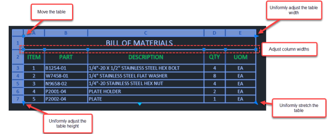
When adjusting the height or width of a table, only the row or column adjacent to the grip changes, and the table maintains its overall height or width. Hold Ctrl when using a column grip to adjust the table size proportionally.

The right-click menu (with multiple cells selected) supplies the merge option.
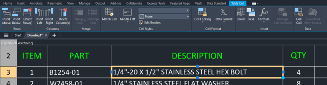
By selecting a cell, the Table Cell contextual ribbon appears. Use the option to insert new rows and columns or to delete the active row or cell. You can select multiple cells by holding Shift as you make selections or by a crossing window. When inserting new rows, AutoCAD inserts rows for the number of selected cells.
Like all AutoCAD styles, Table Styles help keep a uniform and consistent appearance across your drawings. Use the styles to set the default text size, alignment, colors, and borders.
Open the Table Style Manager by typing TABLESTYLE (in the command line), selecting the edit button in the Insert Table dialog, or selecting the dialog launcher from the ribbon. In the Table Style dialog, select New to create a new style or Modify to edit an existing style.
A table style is a collection of cell styles. You can set different cell styles for the table’s data, headers, and title.
AutoCAD distributes the formatting options across three tabs: General, Text, and Borders. Use General to modify the appearance of the cell, Text to manage the text formatting, and Borders to customize cell borders and linework.

Once you have defined a table style, you can apply it to a table by selecting the table and choosing the desired style from the Table Style dropdown ribbon or from the Properties palette.
Tip: You can quickly remove style overrides from the table or specific cells with the Remove All Property Overrides feature from the right-click menu. This provides a quick way to restore a table to its assigned style.
You can break tables horizontally into primary and secondary components. Select the table and enable table breaks in the Properties palette (Table Breaks section). You can also drag the triangular grip to both activate the break and set its position.
The Properties palette presents the options for the table break:
AutoCAD Fields are dynamic text displaying drawing or object property information. This information updates as the drawing or associated object updates. When right-clicking on a cell, you can insert a field, linking the cell to a drawing or object property. For example, displaying the area of a polyline.
It is common to have legends in a drawing that supply a visual representation of the symbol and the corresponding description. AutoCAD tables are perfect for these. You can insert blocks into a cell (from the right-click menu) and use adjacent cells for the text description. The blocks in tables are still blocks, meaning if the definition changes, it updates the instance in the table as well.

When you put a block into a cell, you decide whether the block will adapt to the cell’s size or whether the cell will adjust to accommodate the block’s size. If you will be inserting multiple blocks into a cell, use Manage Cell Content to alter the content display.
Specify the following properties:
AutoCAD Tables support formulas (calculations). Although formulas are not as powerful as spreadsheets, AutoCAD does support formulas for sums, averages, counts and basic arithmetic. This formula capability is useful with data requiring analysis—or when you need to generate summary information based on the table information.

You can insert formulas from the right-click menu, the Table Cell contextual ribbon, or manually when entering text into the cell. When building formulas manually, they must start with an equal sign (=).
As with spreadsheets, you reference cells by their column (letter) and row (number). For example, the first cell (top left) is A1. Define a range of cells by the first and last cells, separated by a colon. For example, the range A3:B10 includes cells in the first two columns, rows 3 through 10.
When manually building formulas, you must type the cell references. When inserting formulas, AutoCAD prompts you to select the cell range. Use the Cell formula to reference a cell in another table (in the same drawing).
Inserting Data Automatically: After entering a date or numeric value into a cell, drag the AutoFill grip to automatically increment values in adjacent table cells.
AutoCAD automatically increments numbers by 1 and dates by 1 day if only one cell is selected and dragged. When multiple cells are selected, AutoCAD determines the increment based on the range between the selected values.
The Data Format is how the cell data is presented or displayed. Start by selecting the Data Type. The default is General, which is a generic type that accepts data of several types. Use Angle, Decimal, Percentage, and Whole Number to manage the display of numbers. The dialog shows a preview of the selected options.
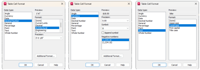
Many Types present Format options relevant to the selected type. For example, with Decimal, you select the desired unit format, like architectural, to display the value in feet and inches. With Decimal, you also set the desired precision.
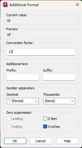
With the Additional Format options, you can further manage the display of the data. This includes prefixes and suffixes, setting the number separators, and what to do with zeroes.
We will not be going into detail here, but it is important to note that the data in your tables can come from three sources.
As this article has highlighted, you can start with an empty table and add text, fields, and blocks to populate it.
Using Data links, you can link your AutoCAD tables to Excel spreadsheets. As the spreadsheet changes, so does the data linked in the AutoCAD table.
The third choice is to use Data Extraction to gather information about the objects in your drawings and present it in a table.
By using tables, you can collect, organize and display structured information. With certain data, tables help express the information and improve readability.
You can see that tables are not difficult and are easy to implement. With the flexibility that tables offer, create basic tables, import data from external sources, or do calculations with ease and precision.